
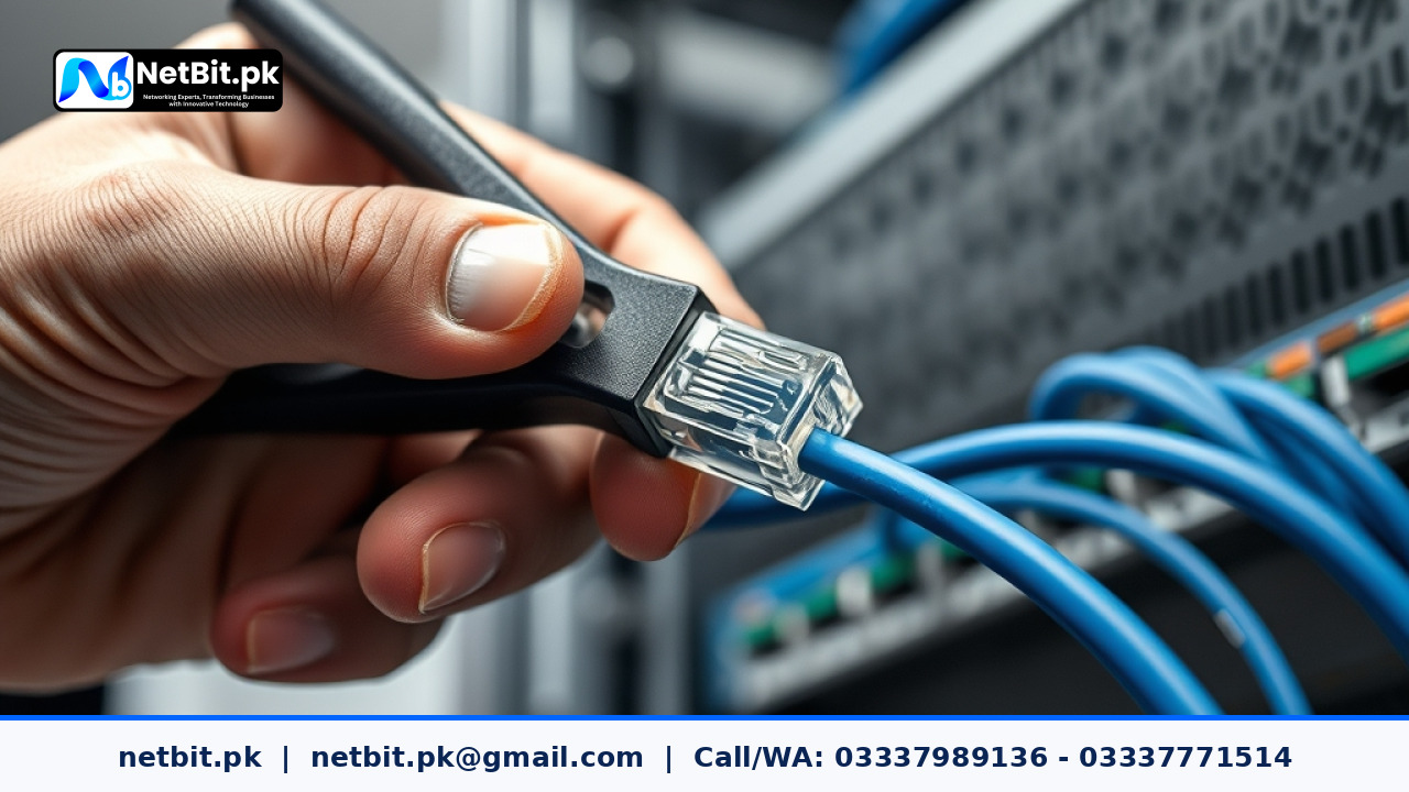
Introduction to Cat6 Cable Termination
Building a stable local network for your office, school, or commercial building starts with reliable physical wiring. While wireless technology has improved over the years, solid copper structured cabling remains the backbone of enterprise networks. Proper cable termination ensures that your computers, switches, patch panels, and CCTV cameras communicate without signal loss, cross-talk, or sudden drops in connectivity.
In Pakistan, office setups frequently experience network degradation simply due to poorly crimped connectors or improper wire arrangement. Learning how to properly terminate Cat6 Ethernet cables allows network technicians, IT staff, and business owners to maintain clean, high-performance office infrastructure. In this detailed tutorial, NetBit Tech outlines the step-by-step process of crimping Cat6 cables using industry-standard methods.
Essential Tools and Materials Required
Before beginning your cable termination, gather all the necessary physical tools. Using specialized tools prevents damage to the delicate internal copper strands and ensures long-lasting electrical contacts.
- Cat6 UTP Cable: High-quality solid copper Category 6 network cable.
- RJ45 Connectors: Cat6-rated RJ45 modular plugs (preferably two-piece connectors with load bars for better alignment).
- Cable Stripper / Utility Knife: Designed to cut the outer PVC jacket without scoring internal wires.
- Ratchet Crimping Tool: A heavy-duty RJ45 crimper designed to press the gold contacts evenly into the conductor wires.
- Wire Cutters / Flush Cutters: For trimming copper wire strands clean and flat.
- Network Cable Tester: An essential diagnostic tool to confirm wire continuity and pinout correctness.
- Strain Relief Boots: Rubber boots to protect the plastic RJ45 clip from breaking.
Understanding T568B vs T568A Cabling Standards
Ethernet cabling uses eight color-coded wires twisted into four pairs. To ensure data transmits correctly between network switches and workstation computers, you must arrange these wires in a specific pinout order at both ends of the cable.
There are two recognized commercial standards: T568A and T568B. In Pakistan and across global business environments, the T568B standard is the widely adopted default for standard straight-through network cables.
T568B Pinout Color Order (Pin 1 to Pin 8):
- Pin 1: White / Orange
- Pin 2: Orange
- Pin 3: White / Green
- Pin 4: Blue
- Pin 5: White / Blue
- Pin 6: Green
- Pin 7: White / Brown
- Pin 8: Brown
To build a standard patch cable or wall drop cable, follow the T568B sequence identical on both ends of the Cat6 wire.
Step-by-Step Guide to Crimping Cat6 Ethernet Cables
Step 1: Slide the Rubber Boot and Strip the Outer Jacket
If you are using a protective strain relief boot, slide it onto the Cat6 cable first with the wide opening facing the end of the cable. Next, measure approximately 1.5 inches (3 to 4 cm) from the cable tip. Use your wire stripper to lightly score the outer PVC jacket. Rotate the stripper around the cable gently so you cut only the outer casing without nicking the insulation on the inner copper pairs. Pull off the jacket to expose the twisted pairs and central spline filler.
Step 2: Remove the Central Spline and Un-twist Wires
Cat6 cables contain a hard plastic cross-web separator running through the center (the spline) which separates the four wire pairs to minimize internal cross-talk. Bend the wire pairs back slightly and cut the plastic spline as close to the jacket edge as possible using flush cutters. Take care not to slice any conductor wires. Once the spline is removed, untwist each wire pair completely down to the base of the jacket and flatten them out using your fingers.
Step 3: Straighten and Arrange Wires According to T568B
Pull each of the eight individual wires straight between your thumb and index finger to remove any bends or kinks. Line up the wires side-by-side in the exact T568B sequence from left to right: White-Orange, Orange, White-Green, Blue, White-Blue, Green, White-Brown, Brown.
Double-check the order carefully under good lighting. A single swapped wire will cause connection failure or force your switch to drop speed to 100Mbps instead of Gigabit rates.
Step 4: Trim Wires to Length and Insert into RJ45 Connector
Once aligned flat and pressed tightly together, cut the tops of the wires using your wire cutters so they form a perfectly straight edge. Leave about 0.5 inches (1.2 cm) of exposed wires extending out from the PVC jacket base.
Hold the RJ45 connector with the plastic retention locking tab facing down (away from your eyes). Firmly push the aligned wires straight into the rear of the RJ45 connector. Ensure that each individual conductor slides into its respective track and reaches the very front wall of the plug. Looking through the transparent front edge of the plug, you should see copper shining clearly at the tip of all eight pin slots. The outer PVC jacket must extend inside the back of the RJ45 body to ensure proper strain relief locking.
Step 5: Crimp the Connector Securely
Insert the prepared RJ45 head completely into the matching 8P8C crimp slot of your ratchet crimper. Squeeze the handles firmly together until the ratchet releases automatically. The crimper forces the brass contacts down through the insulation of each individual wire while simultaneously pinching the rear plastic anchor against the outer PVC jacket.
Slide the rubber strain relief boot over the rear plug housing until it snaps securely into place over the connector tab.
Step 6: Test the Connection with a Continuity Cable Tester
Repeat the termination process on the opposite end of your Ethernet cable. Once both connectors are attached, plug the cable ends into the transmitter and receiver units of your handheld network tester. Turn on the tester and monitor the LED indicator sequence. If all eight numbered LEDs light up sequentially from 1 to 8 on both ends, your cable is properly terminated and ready for operational deployment.
Best Practices for Reliable Office Cabling in Pakistan
- Avoid Over-Untwisting: Do not untwist the cable pairs more than 0.5 inches back from the connector edge. Keeping pairs tightly twisted preserves original signal integrity.
- Avoid Mixing Copper-Clad Aluminum (CCA): Always select 100% Solid Bare Copper Cat6 cables for business installations in Pakistan. CCA wires oxidize quickly and fail under Power over Ethernet (PoE) loads for CCTV and IP phones.
- Observe Bending Radius: Never bend Ethernet cables at sharp 90-degree angles during duct routing or cabinet installation to prevent conductor micro-fractures.
- Maintain Clean Rack Storage: Route patch cords through vertical and horizontal cable managers inside your network rack to eliminate strain on terminated RJ45 heads.
Frequently Asked Questions (FAQs)
Can I connect a Cat6 connector onto a Cat5e cable?
While an RJ45 connector may fit physically, Cat6 wires feature slightly thicker insulation gauge (23 AWG) compared to Cat5e (24 AWG). Using matching Cat6-rated connectors ensures proper electrical pin piercing and mechanical stability.
Why does my terminated cable only negotiate 100Mbps instead of 1Gbps?
Gigabit network transmission requires all 8 wires (all 4 pairs) to make clean contact. If even one pin (such as Pin 4, 5, 7, or 8) fails to terminate cleanly, the network interface controller automatically drops back to 100Mbps 2-pair mode.
What is the maximum functional distance for a Cat6 cable drop?
The standard maximum distance for a single Cat6 copper run is 100 meters (328 feet), which typically includes 90 meters of solid horizontal trunk cabling and 10 meters of patch cords.
Professional IT Infrastructure Services by NetBit Software House
Establishing clean, high-performance office connectivity requires technical skill, precise tooling, and structured execution. At NetBit Software House & Technology, based in Khuzdar, Pakistan, our specialized engineering teams provide end-to-end IT infrastructure, network cabling, rack organization, and hardware deployment services for growing businesses, educational institutions, and corporate facilities.
Whether you require structured Cat6 cabling, fiber optic patch runs, high-grade network switches, Point-to-Point wireless links using LiteBeam and PowerBeam, or enterprise CCTV surveillance installations, NetBit Khuzdar delivers reliable, scalable infrastructure tailored to your operational needs. Contact NetBit Tech today to consult with our network specialists and modernize your business connectivity.



Reader comments.
Share your question, suggestion or experience related to this article.
No comments yet
There are no approved comments on this article yet. You can be the first person to leave one.