
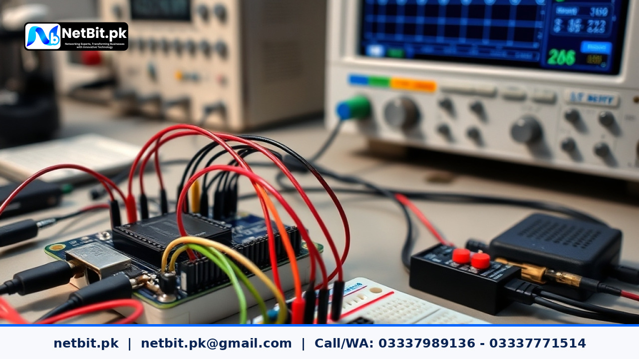
What Is the I2C Bus in Embedded Hardware?
In modern electronic hardware and custom embedded engineering, connecting multiple sensors to a central microcontroller can quickly consume valuable input and output pins. When building custom monitoring units, field loggers, or automation devices, hardware engineers need a dependable way to link chips together without running dozens of individual wires. This is where the Inter-Integrated Circuit protocol, widely known as I2C, becomes essential.
Originally created to allow integrated circuits to communicate easily on a single circuit board, I2C uses only two signal lines to transfer data back and forth between a master controller and several slave devices. For technology enthusiasts, engineering students, and local technicians working with embedded projects at netbit tech, mastering the physical wiring and communication logic of the I2C bus is a fundamental step toward building reliable custom hardware.
The Two Core Lines of an I2C Interface
Unlike serial communication protocols like SPI that require separate chip-select lines for every attached device, I2C keeps the hardware interface remarkably simple by sharing two open-drain signal lines across the entire network:
- Serial Clock Line (SCL): This line carries the clock pulses generated by the master microcontroller. It synchronizes every bit of data traveling across the bus so both sender and receiver read values at the exact same instant.
- Serial Data Line (SDA): This line carries the actual bits of information bidirectionally. Device addresses, register commands, and sensor measurements all travel across this single line.
Because both lines are shared, every peripheral module on the bus listens continuously. The master device initiates communication by sending a unique 7-bit or 10-bit address. Only the module matching that address responds, while all other peripherals keep their output drivers silent.
Why Pull-Up Resistors Are Critical for Stable Signals
One of the most common issues beginners encounter when building hardware prototypes is random communication freeze-ups or missing sensor data. In almost every case, the root cause relates to missing or incorrect pull-up resistors.
The output pins on I2C devices are designed as open-drain (or open-collector). This means a chip can pull the signal line down to ground level (0 volts) to represent a logic low, but it cannot drive the line high to supply voltage (3.3V or 5V) on its own. Instead, external pull-up resistors connect the SCL and SDA lines to the positive power rail.
How Resistor Values Affect Bus Performance
Selecting the proper resistance value requires balancing signal rise time against power consumption:
- Too High (e.g., 20k to 50k ohms): Weak pull-ups cannot charge the tiny capacitance of the PCB traces and connecting wires quickly enough. The square clock pulses turn into rounded curves, leading to missed bits and read errors at higher clock frequencies such as 400 kHz.
- Too Low (e.g., under 1k ohm): Very strong pull-ups pull excessive current. The small output transistors inside the microcontroller or sensors might struggle to pull the line completely down to ground, causing high-voltage logic errors.
- Recommended Range: For standard 100 kHz or fast 400 kHz operations running over short wire lengths, resistor values between 2.2k ohms and 4.7k ohms provide clean, reliable square waves in most custom builds.
Addressing and Bus Collisions Explained
Every device connected to an I2C bus must possess a distinct hardware address. If two temperature sensors or two digital displays share the exact same address on the same physical lines, both will attempt to pull the data line low simultaneously when queried. This causes address collisions, corrupts data packets, and can halt the entire microcontroller program loop.
How to Handle Address Conflicts
When working on specialized boards at netbit software house, developers use three dependable approaches to solve address conflicts:
- Hardware Address Pins: Many sensor breakout boards include solder jumpers or address pins (often labeled A0, A1, or ADDR). Tying these pins to ground or power changes the lowest bits of the device address, allowing two to eight identical chips on the same bus.
- I2C Multiplexers: If you must connect ten identical sensors that have non-configurable addresses, an inexpensive multiplexer chip (such as the TCA9548A) acts as an electronic switch. The main controller selects which channel to talk to before sending commands.
- Secondary Hardware I2C Ports: Many modern microcontrollers, such as the ESP32 or STM32 series, offer multiple physical I2C peripheral controllers inside the silicon. Splitting devices across separate physical pin pairs completely prevents collisions.
Standard Clock Speeds and Distance Limits
I2C was originally designed for chip-to-chip communication across small printed circuit boards. It is not naturally suited for long cable runs across large factory floors or between separate rooms without additional signal drivers.
- Standard Mode (100 kHz): Highly tolerant of noise and slight wire capacitance; ideal for breadboard experiments and basic sensors.
- Fast Mode (400 kHz): The default standard for modern digital sensors, OLED screens, and real-time clock modules.
- Cable Length Guidelines: Keep standard unshielded wiring under 30 to 50 centimeters. If your custom application requires cables longer than one meter, you must lower the clock speed, lower the pull-up resistor values, or use dedicated differential I2C buffer chips.
Step-by-Step Diagnostic Method for I2C Buses
If your microcontroller program fails to detect an attached sensor, follow this structured troubleshooting routine practiced daily by technicians at netbit khuzdar:
- Verify Common Ground: Ensure the ground pin of the microcontroller is firmly connected to the ground pin of every peripheral board. Without a common ground reference, voltage levels cannot be interpreted correctly.
- Check Logic Voltage Matching: Never connect a 5-volt peripheral directly to a 3.3-volt microcontroller without a bidirectional logic level shifter. Feeding 5 volts into a 3.3-volt input pin can permanently damage the processor.
- Run an I2C Scanner Sketch: Flash a simple scanner utility to the microcontroller. The scanner cycles through all 127 possible addresses, listening for an acknowledgment bit. If the scanner returns an address, your wiring and pull-ups are functioning. If the scanner hangs, one of your lines is shorted to ground.
- Inspect with an Oscilloscope: When random dropouts occur during field use, connect a digital oscilloscope to SDA and SCL. Inspect the edges of the wave. Clean, sharp transitions indicate healthy signal integrity, while sluggish ramps point to excessive wire capacitance.
Turn Your Custom Hardware Ideas into Working Systems
Building reliable embedded hardware requires a balance of clean physical wiring, correct electrical calculations, and disciplined firmware design. At netbit tech software house, our technical teams work every day on custom electronic controllers, firmware integrations, and modern automation setups that help local organizations modernize their operations. Whether you are developing an IoT monitoring unit, an automated measurement board, or a dedicated business controller, visiting netbit.pk connects you with experienced engineers who turn complex technical blueprints into durable, real-world systems.
Start Your Next Technology Project with NetBit
Navigating hardware development, component selection, and firmware coding alone often leads to expensive delays, burned components, and endless troubleshooting cycles. You do not have to carry that technical burden by yourself when our dedicated specialists are ready to guide your project from initial design to production. Contact our team at NetBit today through netbit.pk, and let us build your custom software and hardware solutions with the precision and reliability your business deserves.



Reader comments.
Share your question, suggestion or experience related to this article.
No comments yet
There are no approved comments on this article yet. You can be the first person to leave one.